Dear All,
We moved to http://ourtut.blogspot.com .....
Thanks,
Monday, 15 December 2014
Thursday, 27 November 2014
MPLS: OSPF sham-links
Introduction
The provider’s MPLS cloud has three routers namely – R1 (P-router), R2 (PE-R2) and R3 (PE-R3). These routers formed OSPF adjacency with one another. R2 and R3 are iBGP neighbors peering with each other’s loopback address.
The TTL propagation within the MPLS cloud was suppressed with
Reason to use ospf sham link
It is possible that customer’s network has an OSPF backdoor link to each other despite subscribing MPLS service which links customer’s edge routers.
 The OSPF link through the MPLS cloud would be an inter-area link
despite both site-a and site-b links are in OSPF area 0, this poses a
problem if customer wants traffic to traverse from site-a to site-b or
vice versa through the MPLS core. OSPF will prefer the intra-area route,
in this case is the backdoor link which resides in the same OSPF area,
to reach the destination.
The OSPF link through the MPLS cloud would be an inter-area link
despite both site-a and site-b links are in OSPF area 0, this poses a
problem if customer wants traffic to traverse from site-a to site-b or
vice versa through the MPLS core. OSPF will prefer the intra-area route,
in this case is the backdoor link which resides in the same OSPF area,
to reach the destination.
To solve this problem, OSPF sham link is used.
The provider’s MPLS cloud has three routers namely – R1 (P-router), R2 (PE-R2) and R3 (PE-R3). These routers formed OSPF adjacency with one another. R2 and R3 are iBGP neighbors peering with each other’s loopback address.
The TTL propagation within the MPLS cloud was suppressed with
no mpls ip propagate-ttl command. This is to “hide” the number of mpls routers that exist within the provider’s MPLS core.Reason to use ospf sham link
It is possible that customer’s network has an OSPF backdoor link to each other despite subscribing MPLS service which links customer’s edge routers.

R4 and R5 has OSPF backdoor link between them.
To solve this problem, OSPF sham link is used.
Wednesday, 19 November 2014
Dynamic Multipoint VPN (DMVPN) Configuration
DMVPN
(Dynamic Multipoint VPN) is a technique where we use multipoint GRE tunnels
instead of GRE point-to-point tunneling. These multipoint GRE tunnels will be
encrypted using IPSEC so that we have a secure scalable tunneling solution. If
you are unfamiliar with tunneling or IPSEC I highly recommend to check the basic configuration for GRE first and how to configure
an encrypted GRE tunnel with IPSEC. Having
said that let’s look at the configuration of DMVPN. This is the topology that
we will use:

Let me explain this topology to you:
·
R1,R2 and
R3 are able to reach each other using their FastEthernet 0/0 interfaces. I used
the 192.168.123.0 /24 subnet so that they can reach each other.
·
R1 will
be the hub router and R2/R3 will be the spoke routers.
·
R2 and R3
will establish a tunnel to R1 as shown with the green
dotted line.
·
When R2
and R3 want to communicate with each other they will create a spoke-to-spoke
tunnel as shown with the purple dotted line.
·
We will
use the 172.16.123.0 /24 subnet for the tunnel interfaces.
·
Each
router has a loopback interface with an IP address. The routers will reach each
others loopback by going through the tunnel interface.
The
configuration consists of a number of steps:
1. Basic configuration of IP
addresses.
2. GRE Multipoint Tunnel
configuration on all routers
3. Encryption of tunnels using
IPSEC.
4. Routing configuration so the
routers can reach each others loopback interfaces.
Let’s get
started!
Monday, 22 September 2014
Failover on Cisco ASA
Configuring high availability requires two identical ASAs connected to each other through a dedicated failover link and, optionally, a Stateful Failover link. The health of the active interfaces and units is monitored to determine if specific failover conditions are met. If those conditions are met, failover occurs.
The ASA supports two failover configurations, Active/Active failover and Active/Standby failover. Each failover configuration has its own method for determining and performing failover.
With Active/Active failover, both units can pass network traffic. This also lets you configure traffic sharing on your network. Active/Active failover is available only on units running in multiple context mode.
With Active/Standby failover, only one unit passes traffic while the other unit waits in a standby state. Active/Standby failover is available on units running in either single or multiple context mode.
Both failover configurations support stateful or stateless (regular) failover.
Hardware Requirements
The two units in a failover configuration must be the same model, have the same number and types of interfaces, and the same SSMs installed (if any).
If you are using units with different Flash memory sizes in your failover configuration, make sure the unit with the smaller Flash memory has enough space to accommodate the software image files and the configuration files. If it does not, configuration synchronization from the unit with the larger Flash memory to the unit with the smaller Flash memory will fail.
Although it is not required, it is recommended that both units have the same amount of RAM memory installed.
Use Google Chrome as a SSH Client
We always use Putty client software for Secure SSH connection between PC to Router or PC to Firewall.
Today i am going to show you how to use your Google chrome browser as a SSH Client.
Open your Chrome browser and enter chrome://extensions/
then search for Secure Shell chrome extension. Install it
Then after it will prompt you SSH client option

Today i am going to show you how to use your Google chrome browser as a SSH Client.
Open your Chrome browser and enter chrome://extensions/
then search for Secure Shell chrome extension. Install it
Then after it will prompt you SSH client option

Tuesday, 2 September 2014
IP Unnumbered Explained
In this tutorial we will take a look at IP unnumbered and how to
configure it. First of all…what is IP unnumbered and why do we need it?
On a router each interface requires a unique IP address so it can install an entry in the routing table and process IP packets. IP unnumbered allows you to process IP packets without configuring a unique IP address on an interface, this works by “borrowing” an IP address from another interface.
Why would you want this and not just configure an IP address on the interface? To answer that question we have to dive into the past.
Once upon a time we didn’t have VLSM (Variable Length Subnet Mask) and we used classful routing protocols like RIP version 1 and IGRP (the predecessor of EIGRP). This means that the smallest subnet you could use was a /24. When using public IP addresses this is a huge waste of IP space. Take a look at the picture below:

There are 3 routers connected with each other using point-to-point serial links. We have to use two /24 subnets while we only require 4 IP addresses in total…such a waste!
IP unnumbered was created to solve this problem so you didn’t have to waste entire subnets on point-to-point interfaces. It borrows an IP address from another interface so you don’t have to configure one on the point-to-point interface.
On a router each interface requires a unique IP address so it can install an entry in the routing table and process IP packets. IP unnumbered allows you to process IP packets without configuring a unique IP address on an interface, this works by “borrowing” an IP address from another interface.
Why would you want this and not just configure an IP address on the interface? To answer that question we have to dive into the past.
Once upon a time we didn’t have VLSM (Variable Length Subnet Mask) and we used classful routing protocols like RIP version 1 and IGRP (the predecessor of EIGRP). This means that the smallest subnet you could use was a /24. When using public IP addresses this is a huge waste of IP space. Take a look at the picture below:
There are 3 routers connected with each other using point-to-point serial links. We have to use two /24 subnets while we only require 4 IP addresses in total…such a waste!
IP unnumbered was created to solve this problem so you didn’t have to waste entire subnets on point-to-point interfaces. It borrows an IP address from another interface so you don’t have to configure one on the point-to-point interface.
Multiple Spanning Tree (MST)
By default Cisco Catalyst Switches run PVST+ or Rapid PVST+ (Per VLAN
Spanning Tree). This means that each VLAN is mapped to a single
spanning tree instance. When you have 20 VLANs, it means there are 20
instances of spanning tree.
Is this a problem? Like always…it depends, let’s take a look at an example:

Take a look at the topology above. We have three switches and a lot of VLANs. There’s 199 VLANs in total. If we are running PVST or Rapid PVST this means that we have 199 different calculations for each VLAN. This requires a lot of CPU power and memory.
When SwitchB is the root bridge for VLAN 100 – 200 and SwitchC for VLAN 201 – 300 our spanning-tree topologies will look like this:
Is this a problem? Like always…it depends, let’s take a look at an example:
Take a look at the topology above. We have three switches and a lot of VLANs. There’s 199 VLANs in total. If we are running PVST or Rapid PVST this means that we have 199 different calculations for each VLAN. This requires a lot of CPU power and memory.
When SwitchB is the root bridge for VLAN 100 – 200 and SwitchC for VLAN 201 – 300 our spanning-tree topologies will look like this:
Wednesday, 20 August 2014
Data Encapsulation & Decapsulation in the OSI Model
Introduction
Here we are going to explain in detail
how data travels through the OSI model. You must keep in mind that the
OSI model is a guideline. It tells the computer what it's supposed to do
when data needs to be sent or when data is received.
Our Study Case
We are going to analyse an example in order to try and understand how data encapsulation and decapsulation works. This should make it easier for most people.Try to see it this way :
When a car is built in a factory, one person doesn't do all the jobs, rather it's put into a production line and as the car moves through, each person will add different parts to it so when it comes to the end of the production line, it's complete and ready to be sent out to the dealer.
The same story applies for any data which needs to be sent from one computer to another. The OSI model which was created by the IEEE committee is to ensure that everyone follows these guidelines (just like the production line above) and therefore each computer will be able to communicate with every other computer, regardless of whether one computer is a Macintosh and the other is a PC.
One important piece of information to keep in mind is that data flows 2 ways in the OSI model, DOWN (data encapsulation) and UP (data decapsulation).
The picture below is an example of a simple data transfer between 2 computers and shows how the data is encapsulated and decapsulated:

Explanation:
BGP Route Aggreagation
BGP Route Aggreagation helps to reduce the size of the routing table. A
summary route is announced to the peer. The component routes, that make
up the aggregate, can be suppressed or announced additionally to the
aggregate. At least one component route has to be in the BGP table for
the aggregate to be announced.
The BGP setup is as follows. R1 and R2 are in AS 100, R3 is in AS200.

The component routes are announced on R1. As BGP needs valid routes in
the routing table before announcing networks to peers, interface
Loopback 1 is configured with 5 addresses.
The BGP setup is as follows. R1 and R2 are in AS 100, R3 is in AS200.
R1#show running-config inter loopback 1
Building configuration...
Monday, 17 February 2014
Parser View
With CLI view, we can restrict which access each network administrator have based on role.Superviews allow a network administrator to easily assign all users within configured CLI views to a superview instead of having to assign multiple CLI views to a group of users.
Here is the basic configuration of the Parser View.
R2 <----> R3
192.168.1.1 <----> 192.168.1.2
Task:
aaa new-model
!
!
aaa authentication login default local
aaa authentication login VTY local
aaa authentication login CON none
aaa authorization exec default local
aaa authorization exec VTY local
Here is the basic configuration of the Parser View.
R2 <----> R3
192.168.1.1 <----> 192.168.1.2
Task:
- Allowing telnet access with the username OPERATOR and password CISCO to be able to configure the HTTP feature in the router only.
- Configure Username ADMIN and password CISCO to have access to every feature in the router.
aaa new-model
!
!
aaa authentication login default local
aaa authentication login VTY local
aaa authentication login CON none
aaa authorization exec default local
aaa authorization exec VTY local
username OPERATOR view HTTP password 0 CISCO
username ADMIN privilege 15 password 0 CISCO
parser view HTTP
secret 5 $1$6ZRJ$CIjM5cdVUvhpinttlR/361
commands configure include ip http
commands configure include ip
commands exec include configure terminal
commands exec include configure
commands exec include show running-config
commands exec include show
Monday, 20 January 2014
Any Transport Over MPLS (AToM)
Any Transport over MPLS (AToM) will transport layer 2 frames over a MPLS (Multiprotocol Label Switching) network. This will allow service providers to connect layer 2 networks of customers transparently by using their MPLS backbone. AToM can transport the following:
- ATM AAL5
- ATM Cell Relay
- Ethernet
- Frame Relay
- PPP
- HDLC
I will give you an example how to configure AToM to transport Ethernet over the MPLS backbone, we will use the following topology to do this:

Above you see a small MPLS backbone that consists of the PE1, P and PE2 router. This ISP only has one customer that has a HQ and Branch. The customer wants to have the HQ and Branch router to be in the same layer 2 segment.
Cisco IOS NAT on a Stick Configuration Example
NAT (Network Address Translation) is most commonly used to let users on our LAN access the Internet using a single public IP address but it can be used for some more interesting scenarios. Recently I encountered an interesting CCIE R&S task that had the following requirement:
"Make sure that whenever R2 responds to a traceroute it replies with the IP address on the loopback 0 interface"
This sounds easy enough but there’s no such thing as a “traceroute source loopback 0″ command or anything alike. To make this work we have to configure the NAT on a stick feature. In this tutorial I’ll show you this is done. First of all, this is the topology that we will use:

There are only two routers that are directly connected to each other. R2 has a loopback 0 interface with IP address 2.2.2.0 /24. Let’s configure these IP addresses first:
Site-to-Site IPSEC VPN Between Two Cisco ASA – one with Dynamic IP
isco ASA 5500 Series appliances deliver IPsec and SSL VPN, firewall, and several other networking services on a single platform. Cisco ASA 5520, a member of the Cisco ASA 5500 Series, is shown in Figure 1 below.
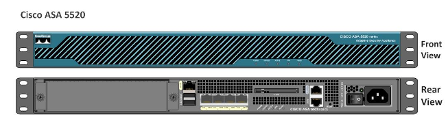
Figure 1 Cisco Adaptive Security Appliance (ASA)
Thursday, 16 January 2014
Site-to-Site IPSEC VPN Between Cisco ASA and pfSense
IPSEC is a standardized protocol (IETF standard) which means that it
is supported by many different vendors. Therefore if you want to create a
VPN between different vendor devices, then IPSEC VPN is the way to go.
In this article we will see a site-to-site VPN using the IPSEC protocol between a Cisco ASA and a pfSense firewall. PfSense is an open source distribution of FreeBSD customized for use as a firewall and router. You can install pfSense on a PC with two (or more) NICs, essentially turning it into a flexible security appliance. You can obtain your copy of pfSense from the Downloads section of www.pfsense.org. At the time of this writing, the latest available release is 2.0.2 and the same has been used in this tutorial.
In this article, we will focus on site-to-site IPsec implementation between a Cisco ASA and a pfSense firewall, as shown in Figure 1 below.
 We will start with a preconfiguration checklist that will serve as a
reference for configuration of IPSEC on both devices. ISAKMP/Phase 1
attributes are used to authenticate and create a secure tunnel over
which IPsec/Phase 2 parameters are negotiated.
We will start with a preconfiguration checklist that will serve as a
reference for configuration of IPSEC on both devices. ISAKMP/Phase 1
attributes are used to authenticate and create a secure tunnel over
which IPsec/Phase 2 parameters are negotiated.
In this article we will see a site-to-site VPN using the IPSEC protocol between a Cisco ASA and a pfSense firewall. PfSense is an open source distribution of FreeBSD customized for use as a firewall and router. You can install pfSense on a PC with two (or more) NICs, essentially turning it into a flexible security appliance. You can obtain your copy of pfSense from the Downloads section of www.pfsense.org. At the time of this writing, the latest available release is 2.0.2 and the same has been used in this tutorial.
In this article, we will focus on site-to-site IPsec implementation between a Cisco ASA and a pfSense firewall, as shown in Figure 1 below.
Figure 1 Cisco ASA to pfSense IPsec Implementation (Click for Larger Picture)
Table 1 Preconfiguration Checklist: ISAKMP/Phase-1 Attributes
Wednesday, 15 January 2014
Another Java zero-day vulnerability being exploited in the wild

Do you still have Java installed? There is a bad news for you ! FireEye has detected yet another Java zero-day vulnerability being exploited in attacks in the wild.
The vulnerability targets browsers that have the latest version of the Java plugin installed Java v1.6 Update 41 and Java v1.7 Update 15 and FireEye warned that the vulnerability is being exploited to install a remote-access trojan dubbed McRat, researchers from security firm.
"Not like other popular Java vulnerabilities in which security manager can be disabled easily, this vulnerability leads to arbitrary memory read and write in JVM process,"
"After triggering the vulnerability, exploit is looking for the memory which holds JVM internal data structure like if security manager is enabled or not, and then overwrites the chunk of memory as zero."
The exploit is reportedly different from the one used to attack Facebook, Twitter, Apple, and several other companies last month.
It is not known if this particular Java vulnerability is on Windows only or on Linux and Mac OS X, too. However, McRat is a Windows Trojan so the in-the-wild attacks are specifically targeting Windows users.
If you don't want any chance of being infected, the best thing to do is uninstall Java altogether.
Old School Hackers spying on European governments

Kaspersky Lab's team of experts recently published a new research report that analyzed that Cyber criminals have targeted government officials in more than 20 countries, including Ireland and Romania with a new piece of malware called 'MiniDuke'.
In a recent attack, malware has infected government computers this week in an attempt to steal geopolitical intelligence. The computers were infected via a modified Adobe PDF email attachment, and the perpetrators were operating from servers based in Panama and Turkey.
According to Kaspersky Lab CEO Eugene Kaspersky,"I remember this style of malicious programming from the end of the 1990s and the beginning of the 2000s. I wonder if these types of malware writers, who have been in hibernation for more than a decade, have suddenly awoken and joined the sophisticated group of threat actors active in the cyber world."

Last week Adobe released an update that patches the Adobe PDF bug (CVE-2013-6040) used in the attack. Once it was opened, the MiniDuke malware would install itself on a victim's computer. It is not known what information the attackers are targeting.
MiniDuke attacks government entities in Belgium, Brazil, Bulgaria, Czech Republic, Georgia, Germany, Hungary, Ireland, Israel, Japan, Latvia, Lebanon, Lithuania, Montenegro, Portugal, Romania, Russian Federation, Slovenia, Spain, Turkey, Ukraine, United Kingdom and United States.
The malware also compromised the computers of a prominent research foundation in Hungary, two thinktanks, and an unnamed healthcare provider in the US.
Monday, 13 January 2014
Mpls Vpn review
Hi all,
I'm completely busy on studying CCIE R&S written but I want to share a mpls vpn lab for reviewing mpls arguments.
Here is the topology:

Task list for this lab is:
-R1-R2-R3-R4-R5-R6-R7 (ISP) cannot elect any DR/BDR to speed up convergence
-Any OSPF area 0.0.0.0 neighbor fault must be detected within 1 second or less (NOTE: if you use dynamips, this requirement can be skipped or "relaxed"..., the high cpu % utilization will bring up/down your adjacency when you perform some operations like enable mpls...)
Mpls Lab #1 : Basic Mpls configuration
Hi all, after a successful BGP exam, now it's time to start with MPLS... nothing better than a basic lab to practice the configurations and show commands.
Here the topology, most of my lab routers doesn't support mpls (2600 series) that's why I used GNS3 with 3600s...
 STEP 1: configure all point to point links and use EIGRP with various AS to route all links and loopbacks. Ensure that you can ping every interface from every router.
STEP 2: basic mpls configuration, for each router you must:
-enable ip cef with:
BGPFLAP: a simple tcl script to flap an interface
Hi all,
today I was trying the bgp dampening feature, and I wrote this simple tclsh script to flap an interface during my lab tests:
first, configure an interface with the route to flap:
then configure the network statement for that route under the bgp process:
and here is the tclsh script, I reccomend a wait time of 40-50 sec with the default bgp timers
today I was trying the bgp dampening feature, and I wrote this simple tclsh script to flap an interface during my lab tests:
first, configure an interface with the route to flap:
R3#sh run int lo 10 | beg int
interface Loopback10
 ip address 10.10.10.10 255.255.255.0
end
then configure the network statement for that route under the bgp process:
R3#sh run | sec router bgp
router bgp 300
 no synchronization
 bgp log-neighbor-changes
 bgp dampening
 network 10.10.10.0 mask 255.255.255.0
 neighbor 192.168.2.1 remote-as 200
 neighbor 192.168.2.1 ebgp-multihop 2
 neighbor 192.168.2.1 update-source Loopback0
 no auto-summary
R3#
and here is the tclsh script, I reccomend a wait time of 40-50 sec with the default bgp timers
Sunday, 12 January 2014
VRRP , An Overview and Implementation
VRRP: Virtual Router Redundancy protocol
To reach remote networks we use the following methods to discover the first hop to our remote network:
- Dynamic process
- Static configurations
The problem with dynamic exploration is extra network overhead, and usually static configuration is recommended as it gives the next hop detail in advance thus reducing the extra network overhead. But the problem with static next hop or in simple words default gateway configuration is redundancy as it creates a single point of failure. To overcome this, we use different redundancy configuration techniques, in which we configure a single virtual IP on a group of routers. In case one virtual gateway fails, the load is instantly shifted to the next available router according to priority. VRRP is one of those techniques as are GLBP and HSRP. In VRRP we define a Master Router and a bunch of back up routers; these backup routers are the point of redundancy in case of Master router failure.

SNMP: Simple Network Management Protocol
SNMP: Simple Network Management Protocol
SNMP is used for monitoring of network devices, collects logs and health statistics of different device nodes. SNMP data can be collected on a centralized NMS (Network Management System), the collected data can be plotted for a better representation of the overall network health. SNMP collects all of its data via SNMP Pooling and SNMP traps. Some famous SNMP supported NMSs are IBM Tivoli, PRTG and MRTG grapher. Many free SNMP based software is also available in the open source community.
Quick Facts about SNMP:
- SNMP Poll uses UDP 161
- SNMP Trap uses UDP 162
- SNMPv3 allows username authentication and packet encryption
- SNMP Inform requires packet acknowledgement, while SNMP Trap does not
- SNMP versions: SNMPv1, SNMPv2c & SNMPv3
SNMP Configuration in GNS3
Suppose, we are setting in a NOC (Network Operations Center). Our network is up and running, our task is to configure an SNMP based NMS to monitor our Core Network Router (R1), which is critical for our network operations. We are using a very popular NMS, known as PRTG (Packet router traffic Grapher). PRTG is a very popular used NMS, very good, efficient and excellent graphical interface, which gives us a very remarkable view of our critical network elements.
The simple flow of the topology is as follows:
A 2691 router is connected to a cloud (in GNS3, Cloud is used to connect the router to our PC physical interface). PRTG NMS has been configured on PC1 (local host). The topology is given below:

Subscribe to:
Comments (Atom)